
распиновка USB pinout Энергетические технологии, Электронная схема
USB pinout signals. USB is a serial bus. It uses 4 shielded wires: two for power (+5v & GND) and two for differential data signals (labelled as D+ and D- in pinout). NRZI (Non Return to Zero Invert) encoding scheme used to send data with a sync field to synchronise the host and receiver clocks. In USB data cable Data+ and Data- signals are.
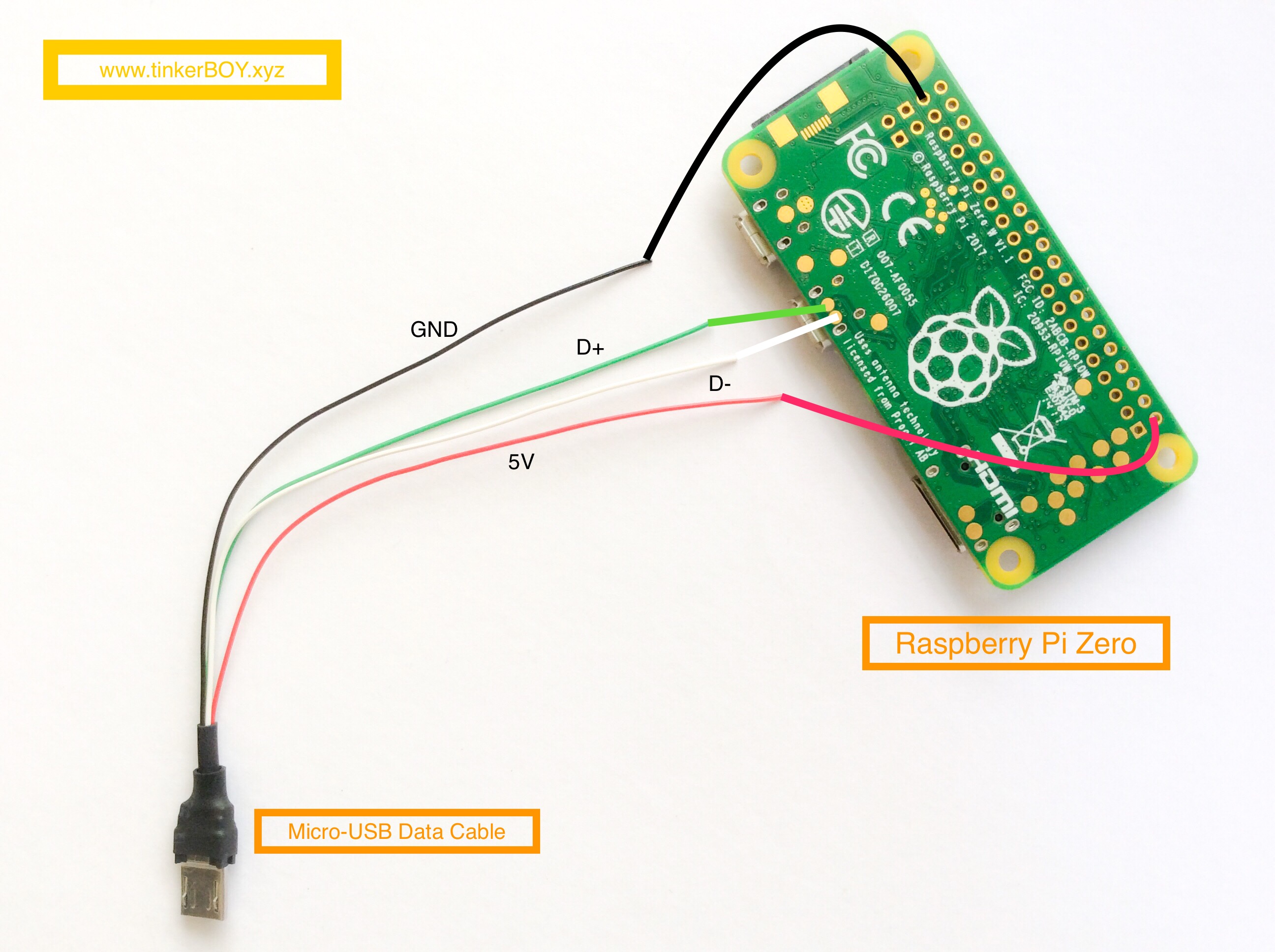
How To Wire The Micro USB 4Wire Data Cable tinkerBOY
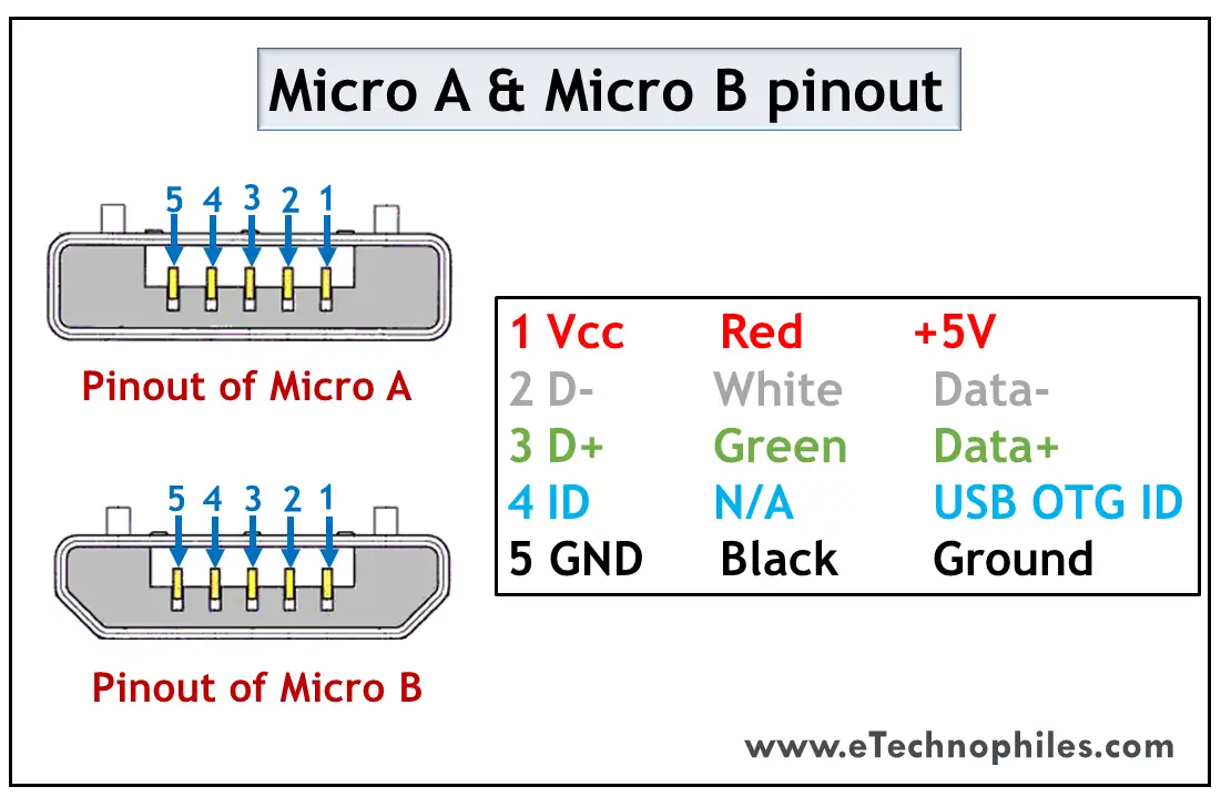
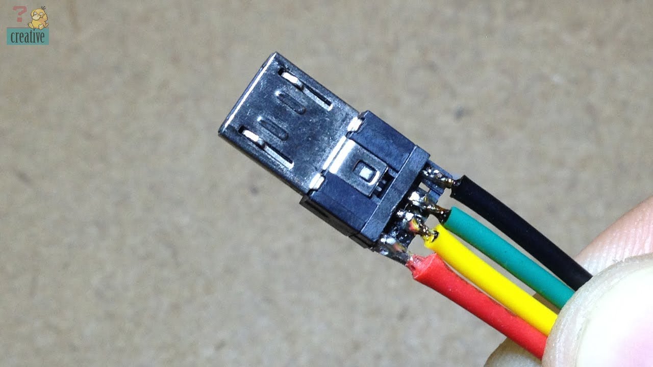
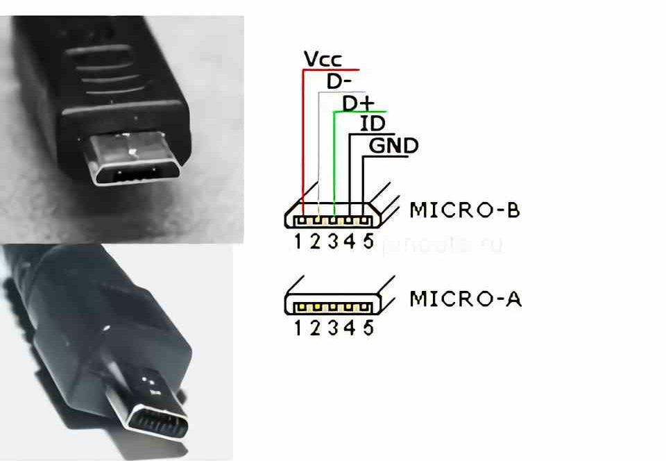
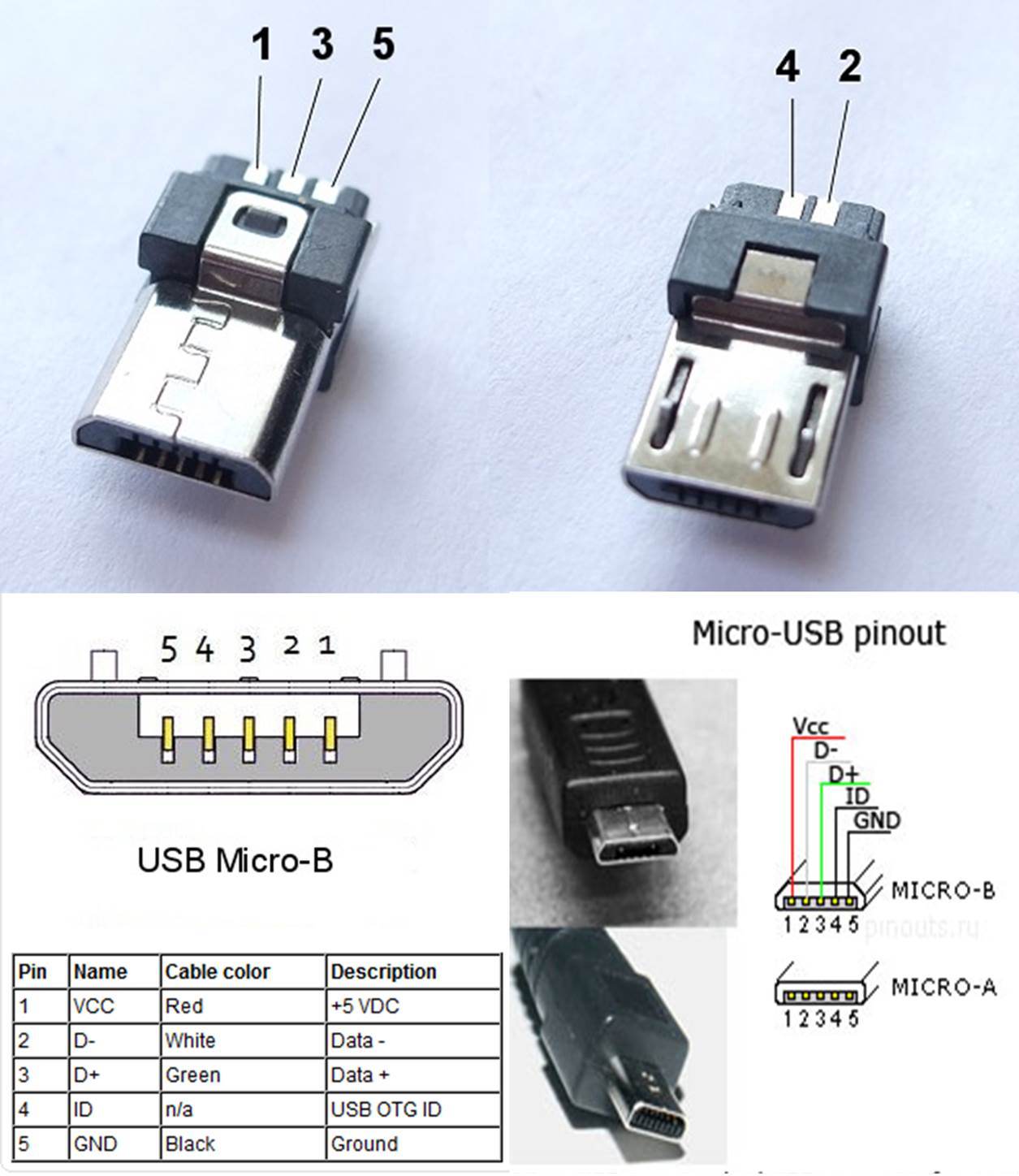
The micro USB Jack has five pins through which the power and data is transferred, the 4th pin ID is used for mode detection, this indicates if the USB is used only for power or for data transfer. Of the remaining four pins two pins (pin 1 and Pin 5) are used to provide the Vcc and Ground. The supply voltage of Vcc is +5V and is usually provided.

4 Pin Micro Usb Wiring Diagram
12 min A Complete Guide to USB Connectors Our USB connectors guide explains their purpose, uses, and the different types and standards available. Topics Covered in this Guide Reviewed by Jay Proctor, Technical Support Team Leader (November 2021)

USB Pinout, Wiring and How It Works ElectroSchematics
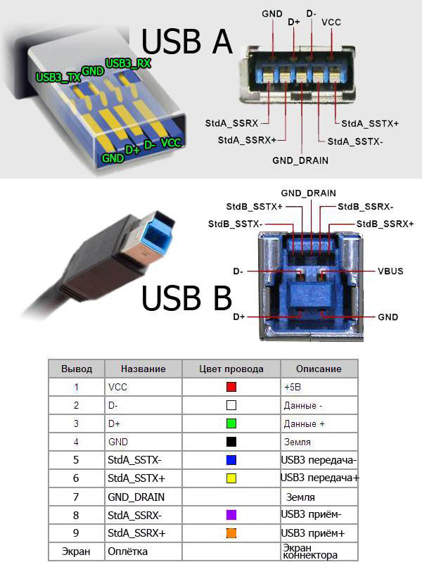
The pinout explanation of USB is shown below: USB Pinout. USB connectors have multiple pins, each serving a specific purpose. The two most common types are USB Type-A and USB Type-B connectors. USB Type-A typically has four pins, while USB Type-B has five pins. The basic pinout for a USB Type-A connector is as follows:

Usb A To Usb A Wiring Diagram Fab Base
Who knows what the future reserves? USB Connections Each USB device uses the standard A type connector to the USB host or Hub through A type receptacle. The other end of the cable has series B connector which is used to plug into the B type receptacle.

Usb Wiring Pinout
The three sizes of USB connectors are the default, or standard, format intended for desktop or portable equipment, the mini intended for mobile equipment, which was deprecated when it was replaced by the thinner micro size, all of which were deprecated in USB 3.2 in favor of Type-C.
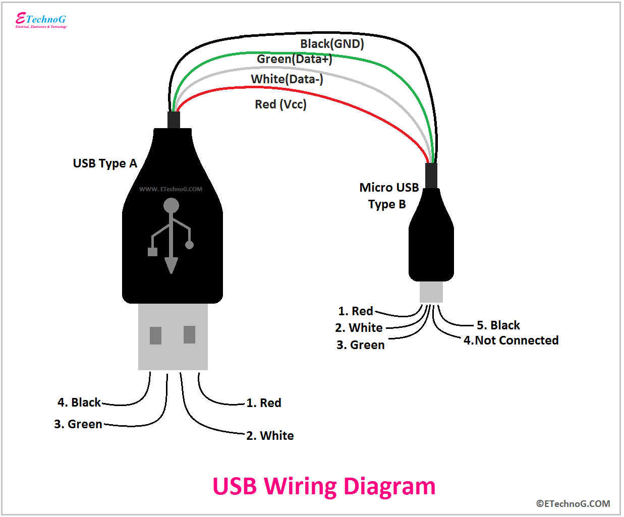
USB Wiring Diagram, Connection, PinOut, Terminals ETechnoG
June 7, 2022 by Ankit Negi Micro USB cables are some of the most common types of charging and data transfer cables used today. They have a small, rounded connector that fits into a variety of devices, making them versatile and easy to use. But what is micro USB, exactly? And why is it so popular? Read on to find out! What is a Micro USB?

Micro Usb Wiring Schematic
USB pinout is the connector's pin configuration and how it transfers data and power. Each USB connector has a unique pinout and function. Depending on the connector, USB has four or five pins. Type-A, Type-B, Mini-USB, and Micro-USB connectors are the most popular.
What is Micro USB Pinout and Types (FAQs)
The fourth pin (mode detect) is also commonly referred to as USB "On-the-Go" or simply "OTG." This pin allows devices to switch between host and peripheral roles.
10pcs/bag YT2153Y Micro USB 4pin Male Connector Plug White/black
Both of them have 4 pins. The figure below shows the Pinout of Male and Female versions of both USBs. Note: The Female version is actually the USB connector pinout(Connector of a Keyboard for example) and the male version is the USB port pinout( Ports on your laptop for example) USB type A and B ( Male and Female) pinout
Wiring Micro Usb Connector
Micro-USB cable uses 4 shielded wires: two for power (+5v & GND), two for differential data signals (labelled as D+ and D- in pinout). NRZI (Non Return to Zero Invert) encoding scheme used to send data with a sync field to synchronise the host and receiver clocks. In USB data cable Data+ and Data- signals are transmitted on a twisted pair.
Typy USB konektorů A, B, C, MicroUSB a MiniUSB ITIGIC
Pin no. 4 is used as ground. The color code for the wire used in the USB cable red, white, green, grey, black for pin numbers 1, 2, 3, 4 and 5. Please take note of type-A & type-B have the same pinout diagram after arranging on the basis of similarity of shape. Also check, USB OTG wiring diagram & USB C pin diagram and wiring color code
Micro кабель usb технические характеристики
Universal Serial Bus (USB) is an interface to establish communication between devices and a host controller (usually personal computer). Nowdays USB has replaced a variety of earlier PC interfaces (such as RS-232 serial, parallel port , and even FireWire ).
4 Pin Micro Usb Wiring Diagram Network Cable Pinout. Network Cable USB
USB-A. USB-A, or USB Type A, is the original flat and rectangular connector that no one could ever figure out how to plug in correctly the first time. These cables always have USB-A on one end with a different port type on the other, and can be used for device charging and data transfer. USB-A is still widely used and can be found on devices.
USB cable pinouts pinouts and color schematics for 2.0, 3.0, micro and
Symmetrical connectors that can be inserted either way, right side up or upside down. Tested with up to 10,000 connection cycles and is 6 times more durable than USB-A. USB-C can carry USB 4, Thunderbolt 4, Thunderbolt 3, USB 3.2, USB 3.1, USB 3.0, USB 2.0, and USB 1.1 signals.
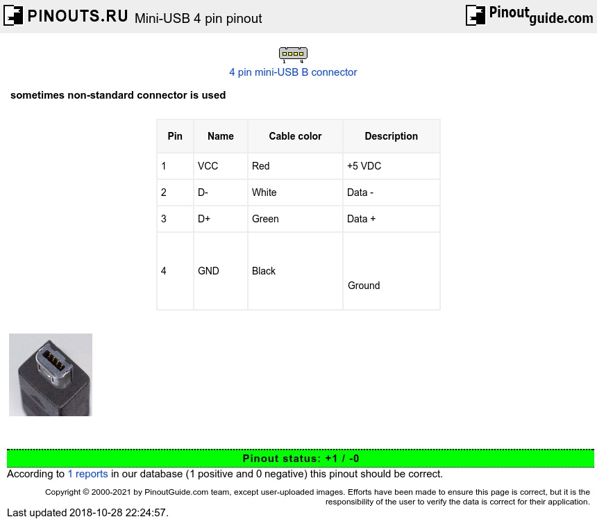
MiniUSB 4 pin pinout diagram
In a USB connector, there are four pins: VCC, D+, D-, and GND. VCC stands for voltage supply, and it provides power to the connected device. D+ and D- are the data pins used for transmitting data between the device and the computer. GND is the ground pin, which completes the electrical circuit and ensures proper functioning.